25+ data flow diagram and entity relationship diagram
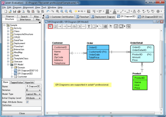
Database designs also include ER entity-relationship model diagramsAn ER diagram is a diagram that helps to design databases in an efficient way. Customization of diagrams and object appearance is possible.

What Is The Entity Relationship Model Diagram Examples Video Lesson Transcript Study Com
Attributes in ER diagrams are usually modeled as an oval with the name of the attribute linked to.

. This section cited in 25 Pa. Avoid to define too many output DTOs for same or related entities. Entity-relationship modeling or ER Diagram symbols are part of a conceptual approach to design that models objects as abstract data types and the relations between these objects as predicates.
Google Cloud Platform Diagram 54. Do define DTOs based on the DTO best practicesOutputs. You can use it as a flowchart maker network diagram software to create UML online as an ER diagram tool to design database schema to build BPMN online as a circuit diagram maker and more.
Code 7355 relating to elevated sand mounds. Lets begin with TM mode. Latin lingua Latīna ˈlɪŋɡʷa laˈtiːna or Latīnum laˈtiːnʊ is a classical language belonging to the Italic branch of the Indo-European languagesLatin was originally a dialect spoken in the lower Tiber area then known as Latium around present-day Rome but through the power of the Roman Republic it became the dominant language in the Italian region and subsequently.
The ER Diagram show the relationship between entities tables and the primary key-foreign key relationships between the tables relationships. To start drawing the Visio process flow diagram we will first have to open the Visio software via Microsoft 365. Code 7353 relating to seepage beds.
One of the first uses of the term protocol in a data-commutation context occurs in a memorandum entitled A Protocol for Use in the NPL Data Communications Network written by Roger Scantlebury and Keith Bartlett in April 1967. Entity-relationship ER data models use formal diagrams to represent the relationships between entities in a database. The entity type being configured will be the dependent and contain a foreign key to the principal.
The entity type that the relationship targets will be the principal in the relationship. The data flow here looks something like this. Entity Relationship Diagram ERD The Entity Relationship Diagram ERD is included in this walkthrough as a quick look at the.
Entity relationship diagrams are used in software engineering during the planning stages of the software project. Techno-functional Dynamics 365 FS Data Model Explanations for Reporting Part 4 of 25 Purchase Order Invoice Posting. From the MSDN Configures the relationship to be required.
As you see in the following diagram TM is the simplest RLC mode. Follow these simple steps to create a process flow diagram in Visio. The term Transparent may have many different meaning.
These interconnections are made up of telecommunication network technologies based on physically wired optical and wireless radio-frequency. Do not getreturn entities for the service methods. Do create DTOs Data Transfer Objects for inputs and outputs of the service.
Here is the functional process flow for a process of sales order invoice posting. Lets have a look at the Entity Relationship Diagram ERD which shows all the cardinality constraints relationship among the tables. Flowchart Maker and Online Diagram Software.
Several ER modeling tools are used by data architects to create visual maps that convey database design objectives. Entity Relationship Diagram 25. Then you will have to click on the category that mentions the process flow diagram so that you can start with your work.
Repositories also support the purpose of separating clearly and in one direction the dependency between the work domain and the data allocation or mapping. On the ARPANET the starting point for host-to-host communication in 1969 was the 1822 protocol which defined. You can export a diagram to numerous formats including BMP JPEG PNG and more.
7 shows a flow diagram of a computer-implemented method using a vector or embedding according to another exemplary embodiment of the present disclosure. Object-oriented data models gained traction as object-oriented programming and it became popular in the mid. Here is the functional process flow for a process of purchase order invoice posting.
Techno-Functional Dynamics 365 FS Data Model Explanations for Reporting Part 10 Of 25 Sales Order Invoice Posting. It allows you to edit entity relationship diagram. Instead define a basic and a detailed DTO for an entityBasic DTODo define a basic DTOCheck out AutoMapper or ValueInjector.
Code 7163 relating to retaining tanks. A computer network is a set of computers sharing resources located on or provided by network nodesThe computers use common communication protocols over digital interconnections to communicate with each other. Entity relationship diagrams in software engineering.
8 illustrates an exemplary block diagram of a computer or processing system in which processes involved in the system method and computer program product described. Code 7354 relating to subsurface sand filter beds and trenches. RLC Uplink Data Flow Example Overall Data Flow for TM RLC.
Business Process Diagram 23. It is often used as the basis for data flow diagrams or DFDs as they are commonly known. They help to identify different system elements and their relationships with each other.
Use Lucidchart to visualize ideas make charts diagrams more. Code 7344 relating to pressurized distribution design. Repository receives a domain Entity from application service maps it to database schemaORM format does required operations saving.
Relationship - an association among two or more entities occurrence - instance of a relationship is the collective instances of the related entities. Drawio can import vsdx Gliffy and Lucidchart files. Required without a navigation property on the other side of the relationship.
For this section as well lets start reading diagram from the specification. An entity is a thing person or. It can generate reports that describe database objects within a diagram.
Ad Get the most powerful professional diagram software on the market. Entity-Relationship ER Modeling Basic ER Modeling Concepts Entity - a class of real world objects having common characteristics and properties about which we wish to record information. TM stands for Transparent Mode.
Database Designer for MySQL helps you to edit and execute SQL scripts. Physical Data Flow Diagram Example.

Pin On Software Development Entity Relationship Diagram Erd

Data Flow Diagram Template Mural
What Is An Erd And Why Do We Use Them Quora

Data Flow Diagram Template Mural

Data Flow Diagram Template Mural

What Is The Entity Relationship Model Diagram Examples Video Lesson Transcript Study Com
How Is Cardinality Written In An Er Diagram Quora

Verifying Use Cases Data Flow Diagrams Entity Relationship Diagrams And State Diagrams Via State Linkag Relationship Diagram Data Flow Diagram State Diagram

What Is The Entity Relationship Model Diagram Examples Video Lesson Transcript Study Com

Standard Flowchart Symbols And Their Usage Basic Flowchart Symbols And Meaning Workflow Di Relationship Diagram Electrical Circuit Diagram Workflow Diagram

Data Flow Diagram Template Mural

Basic Database Diagram Relationship Diagram Diagram Design Relational Database
Data Flow Diagram Template Mural
Er Diagram Entity Relationship Diagram

Jabir7788 I Will Design Unique Infographic Flowcharts And Any Diagram For 5 On Fiverr Com Infographic Flow Chart Process Chart

Erd Diagram Data Flow Diagram Flow Chart Process Flow Chart
What Are The Best Free Online Tools To Draw An Erd Entity Relationship Diagram Quora